Assembly Notes
Required Hardware Modifications
The following hardware modifications are required before/during assembling each reader unit.
- Remove LoRa IC (SX1278) from ESP32 TTGO dev board:
- Remove OLED screen screws.
- Use hot air / reflow tool to remove the SX1278 IC from the board and clean the traces.
- Replace the OLED screen screws.
- Disable pin 12 for Y-axis input GPIO, use pin 14 instead:
- When soldering the male header pins to the ESP32 TTGO dev board, cut/remove the header pin for pin 12.
- Make a solder bridge on the bottom of the PCB, shorting pin 12 and pin 14..
- Disable automatic card read beep on new RFID readers:
- Obtain the HID Global configuration card from the ACM parts kit.
- Power off the new RFID reader unit.
- Place the configuration card within scanning range of the reader (still off).
- Apply power to the system while holding the card in position, and wait for the RFID reader to begin flashing red/purple (may require several seconds).
Wiring and Machine Connections
4-pin X/Y Motor Connector
The 4-pin X/Y motor connector is connected to the Pulse diode pins on the X/Y motor controllers. The measurement is isolated and should be able to measure a wide range of signals with the current voltage divider values for R3 (680), R4 (680), R5 (470), R6 (470).
3-pin IoT Relay Connector
The 3-pin IoT relay connector has inverted logic which expects the safety equipment to be plugged into the "Normally Closed" side of the IoT relay power bar. In this configuration, a power fault or other error should activate the safety equipment until the fault can be restored.
2-pin Interlock Connector
The 2-pin Interlock connector should be connected in series with the interlock circuit of the machine. The output is connected OPEN / CLOSED via a solid-state relay (SSR) on the PCB.
Power-On Behaviour
The initial state of the IoT relay at boot (or after error recovery) is ON. This is a safety-first guess, and the correct state of the relay will be set after the first tag is scanned.
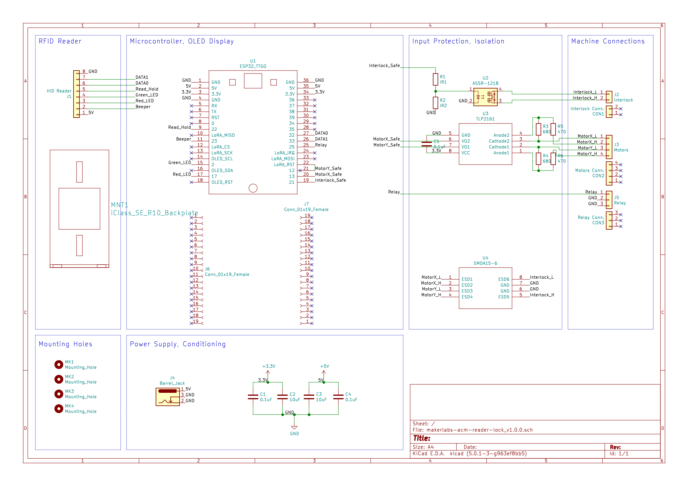
Schematic
makerlabs-acm-reader-lock-v1.0.1 - Schematic
PCB
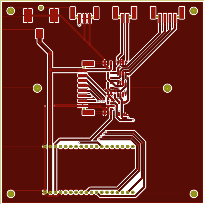
Top Layer
makerlabs-acm-reader-lock-v1.0.1 - Top PCB Layer
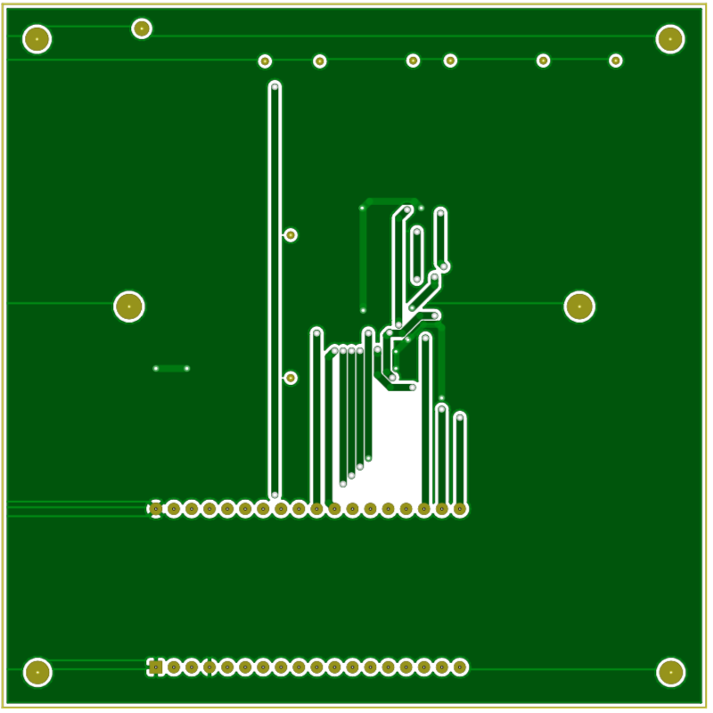
Bottom Layer
makerlabs-acm-reader-lock-v1.0.1 - Bottom PCB Layer
Bill of Materials (BOM)
Generating from KiCad / KiBOM
The KiBOM KiCad (Python) plugin is used from within the KiCad schematic editor to generate a BOM file in CSV format. The values are stored in the schematic part libraries for each part.
- Note
- The special fields used within each part (e.g.
MFN/MFP, S1PN/S1PL) come from the following KiCad BOM article: https://rheingoldheavy.com/kicad-bom-management-part-1-detailed-components/
To (re)generate the BOM CSV file:
- Clone the KiBOM Python plugin:
git clone https://github.com/SchrodingersGat/KiBoM
- Open the KiCad schematic editor, and the target schematic.
- Click the BOM icon near the top-right
- If
KiBOM_CLI is not yet in the Plugins: list
- Click
Add Plugin
- Navigate to the
KiBOM_CLI.py from the git repo cloned in step 1.
- Ensure the
Command line: setting is similar to the following, noting that the output file should end in _BOM.csv python "<full/path/to/KiBoM>/KiBOM_CLI.py" "%I" "%O_BOM.csv"
- Click the "Generate" button to generate a new CSV file.
BOM CSV
makerlabs-acm-reader-lock-v1.0.0 - BOM
API Reference
electrical/ KiCad Project Files Overview